USB phone charger on batteries
Earlier I built a portable phone charger for a Siemens mobile phone. Since I don't use that phone anymore and recent phones can usually be charged with a USB connector I built a new version of the charger. This time with a proper PCB, a USB connector and a higher current capability.
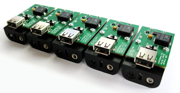
In fact, to reduce costs I built five :)
Schematic
Just as the previous charger it is basically just a step-up converter largely built according to the datasheet. In this case I used the TPS61032 because of its high efficiency, low minimum input voltage (1.8V) and high internal switch current (4A). I wanted the converter to be able to deliver about 1A at 5V, which requires an average input current of 2.5A at 2V input but the peak current can be much higher. The converter is synchronous, which eliminates the need for an external Schottky diode (and its relatively large power loss).

This version also includes a low battery led which turns on when the input voltage is around 1.95V. At this voltage the batteries will soon drop out. The step-up converter can run down to 1.8V but usually when the two batteries are at this voltage there is not much energy left and they will soon drop even lower than 1.8V. Batteries with high internal resistance may come very close to 1.95V even when not empty, so make sure you use good quality rechargeable batteries with low internal resistance. Because the low battery output of the converter can only sink up to 100µA (active low) I added a small P-channel mosfet to be able to drive a LED from it.
I also added a little switch that determines what's connected to the D+ and D- data pins on the USB connector. It switches between two common configurations for USB chargers. One is around 2.0V and 2.75V on D+ and D- respectively, which is what Apple's iPhone wall charger does (as well as the Belkin ones). An iPhone will charge at 1A with this configuration. See also the mysteries of Apple device charging by ladyada who figured it all out. The other setting connects D+ and D- with a 100Ω resistor. This is according to the USB battery charging specification, which requires a resistance of less than 200Ω between the data pins to indicate the USB port can be used for charging. In fact the standard states a maximum of 1.5A which is more than this charger can handle but most phones will use a current below 1A. An iPhone can also detect this setting, but will charge at 500mA instead. I built the charger for my iPhone, effectively having a switch between 1A and 0.5A charging current. That might not be the case on other phones but most phones will charge with at least one of the switches. I've tried it out on an Android phone and this also works, although I haven't measured the current (I believe it is around 700 or 800mA).
All the parts from the resistors to the screws are from digikey, you can lookup the part list below. Total cost based on PCBs and parts for 5 pieces is around €20 per charger.
| Part | Description |
|---|---|
| IC1 | TI TPS61032 5V boost converter |
| L1 | Wurth WE-HCI 7443550820 inductor 8.2µH 10A 11.6mΩ |
| C1 | Ceramic capacitor 10µF X7R 0603 6.3V |
| C2 | Ceramic capacitor 2.2µF X7R 0603 6.3V |
| C3 | Tantalum capacitor 220µF 6.3V Kemet T520 series |
| C4 | Ceramic capacitor 100nF X7R 0603 |
| LED1 | Red low current LED 0603 (OSRAM SmartLed) |
| Q1 | P-channel mosfet BSS84LT1 130mA 50V |
| USB | USB A receptacle Amphenol UE27AC54100 |
| R1, R3 | Resistor 1.1MΩ 1% 0603 |
| R2 | Resistor 1kΩ 0603 |
| R4 | Resistor 390kΩ 1% 0603 |
| R5, R8 | Resistor 33kΩ 1% 0603 |
| R6 | Resistor 22kΩ 1% 0603 |
| R7 | Resistor 27kΩ 1% 0603 |
| R9 | Resistor 100Ω 0603 |
| SW1 | C&K JS202011SCQN Slide switch DPDT |
| BAT | MPD BH2AA-PC 2x AA battery holder |
| Screws | B&F Phillips 2-56x1/4 screws (PMS 256 0025 PH) |
| Nuts | B&F hex nut 2-56 (HNZ256) |
PCBs
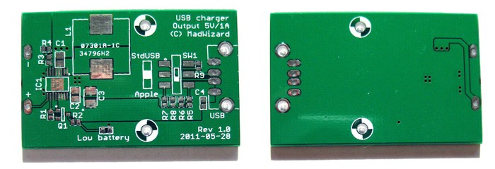
The PCBs are made by iTeadStudio for about €10 for 10 pieces (I actually got 12). Quality is good, silkscreen is a little thick on some of the boards and the HASL finish is not as flat as ENIG but perfectly usable.
Soldered boards
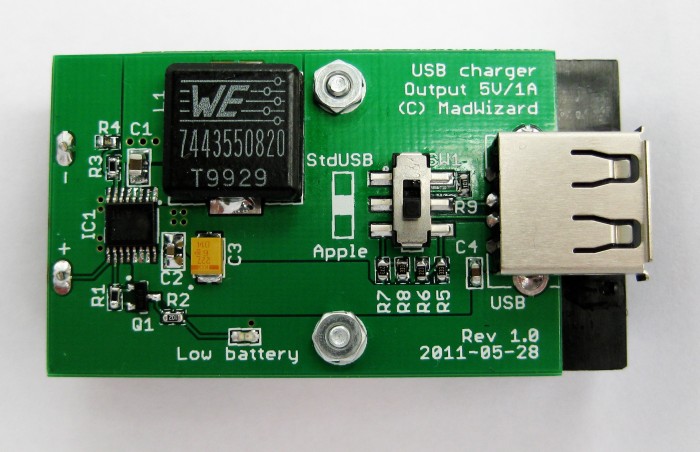
When the boards were built I found out the battery connector pins aren't actually centered which I foolishly assumed they were but that could be fixed easily by bending them a little. The boards fit nicely onto the battery connector. If you're wondering why the board doesn't extend al the way to the edges, it is because iTeadStudios has a size limit of 5x5cm for the cheapest price category, and paying twice as much (10x10cm) wasn't worth it.
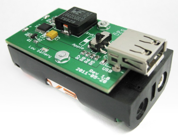
I used a hex nut as a spacer since the USB receptacle needs a little room for its through hole pins. In fact I had to clip the pins a little to reduce the spacing between the battery holder and the PCB, but it's still soldered rock solid.
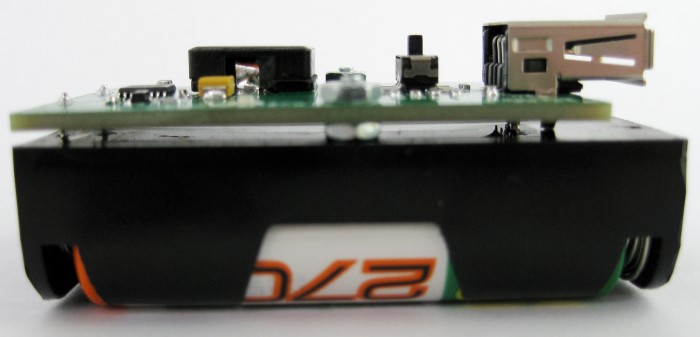
The regulator has a heat transfer pad on the bottom so you really need hot air or a reflow oven to solder it, or maybe you could get away with placing a few vias below it and soldering it from below.
Result
The charger works fine, although high output currents mean even higher input currents that ask a lot from the batteries and they drain fast. Also, at currents of about 2 to 3A every small resistance (battery contacts, PCB traces etc.) counts and takes away from the input voltage, which is only just above the minimum input voltage to begin with. Still, I was able to charge my iPhone 4 from 20% to around 88% in about 75 minutes using freshly charged Eneloop XX 2500mAh batteries. I have also had good results with GP batteries but the Eneloop ones have a lower internal resistance resulting in a higher voltage for a longer time. If you want to built this yourself use high capacity NiMH batteries, preferably low self-discharge ones (LSD NiMH) like Eneloops.
Lower charging currents are more efficient than higher charging currents, but obviously the time to charge will also be longer.
Downloads and part list
You can download the schematic and PCB here, you're free to use them for personal use.
Note: There are two small mistakes in the board, the battery plus and minus connectors are centered on the board but actually they are not centered on the battery holder. I fixed this by bending the pins of the battery holder a bit but if you want to make the PCB yourself you might want to fix this. The second is that C2 has a 0805 footprint although I used a 0603 capacitor (not really a problem). Also, if I would make the board again I'd thicken the VBAT trace on the bottom and maybe add some more vias, since at high currents even the small resistance of these traces can add a relatively significant voltage drop.
Download usbcharger.zip (17.3 KB)