AVR mod player
In 2006, I took part in an electronic demo competition on a Dutch forum (see this topic). Because computer demos like they used to have on old machines like the Amiga or Commodore are harldy made anymore since hardware has come such a long way, someone had the idea to do the same, but on home built hardware. You could use things like a simple microcontroller but not a complete PC or powerful development board, and had to make something with cool graphics, audio, etc.
The competition never really ended properly since most contestants did not have enough time to finish their projects. I came a long way, at least the audio part was working very well but the video part was both poorly designed and never finished.
My idea was to use an oscilloscope as the video output device to show some vector graphics, and create a mod player to provide the audio. The video part of the project had some design flaws and terrible noise in the DACs so I never really finished that part. Also, the audio part was much more fun. The modplayer was built using an ATmega325, an 4MBit parallel flash memory (AT49F040A) and an op-amp to amplify the audio.
MOD file format
The MOD file format is a combination of audio samples and a set of notes on a timeline. FastTracker was one of the programs you could use to edit MOD files, although it was mainly used for the superior XM format.
![]()
A maximum of four channels can be used in a MOD, each can play one sample at a time from the sample set. The sample is played at a specific pitch depending on the note in the channel. Additionally, effects can be added to the notes such as volume or pitch fades.
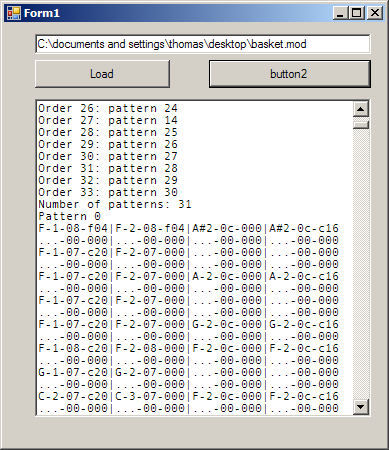
To get familiar with the details of the MOD format I first wrote a C# program that displayed the patterns in the MOD and could also play the MOD file:
Prototype
After that I wrote a converter for the MOD into a slightly different format that was nearly the same format but in an easier to handle structure. Then I built a prototype with an ATmega32 on a breadboard. Because no external flash was used in the prototype the MOD had to fit in the 32KB flash of the AVR along with the firmware which limited the prototype to very small MOD files. But it worked.

Final design
With the prototype working the final design was made. The audio part of the schematic looks like this:
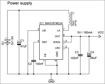
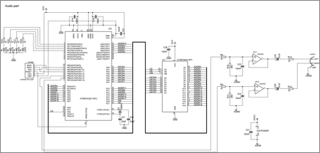
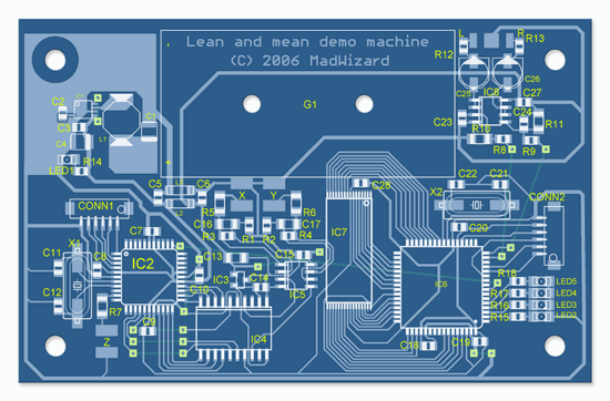
A PCB was designed as well, a large part is for the video part, only the right half (from IC7 to the right) and the power supply (top left) are needed for the audio.
Hardware
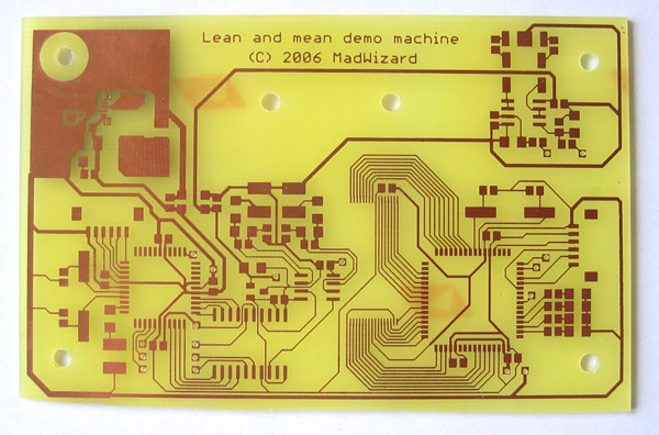
The etched PCB:
For the housing I bent a small piece of acrylic glass with a heat gun and placed the connectors and switch. The three BNC connectors were for the video part. The two RCA connectors are left and right audio channels and the switch is the power switch.

Some of the components that needed to be soldered:

The PCB soldered:
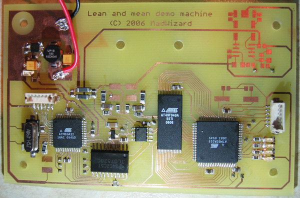
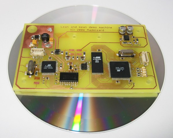
And placed on its housing:
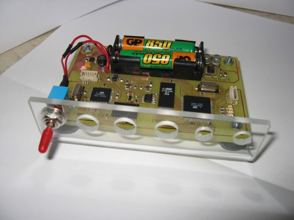
Finally, it looked like this:


Firmware
The audio was generated with the PWM channels of the AVR at a rate of 31.25 kHz. Every output sample the four channels needed to be mixed from four different samples playing at different rates. Amazingly the AVR managed to achieve this. The complete MOD file was stored in the parallel flash, the note patterns as well as the samples had to be read from this flash memory. For each output sample the frequency, volume and sample to use was determined to calculate the right offset in at most four samples. These samples were then read from the flash and mixed together. The output is used as a PWM duty value, passed through an RC filter and buffered by an op-amp.
Video demo
Here you can see the modplayer in action. Each LED stands for one channel and lits when that channel is active:
Here is another demo, "Jammin' for nothing" (from modarchive.com) but with CCFLs connected instead of LEDs, just to see what it would look like :)
The sound in both videos is recorded directly from the AVR.