Playing video from flash memory on Nokia LCD
A lot of shops sell separate mobile phone LCDs, some of which are quite easy to control by home built electronics. In 2006 I got a bunch of Nokia 6100 LCD clones from sparkfun and decided to built a small video player with it. I also bought a set of Altera MAX II CPLDs at the time and this seemed like a good project to get some experience with CPLD and FPGA designs.
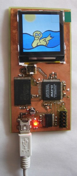
Memory
A video player with clever encoding like MPEG4 was out of the question with such a simple setup, so I used basically a stream of raw bitmaps for the video stream. It takes up a lot of memory for a short video but it is easy. So first of all I needed a lot of memory. Luckily my brother's MP3 player finally broke down after two earlier repairs and I desoldered the NAND flash memory inside it:
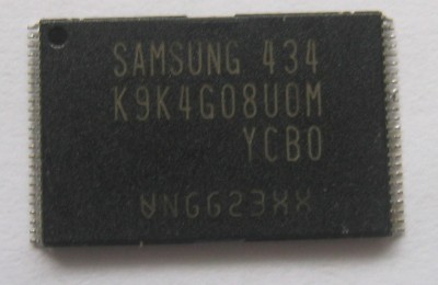
This kind of flash memory (often made by Samsung) is used a lot in USB sticks and MP3 players. This is a 512 MByte flash memory. It has an 8-bit multiplexed data and address bus along with some enable lines.
Schematic
The most important component is the MAX II CPLD, an EPM240 with 240 logic elements. The MAX II is a powerful CPLD but this is the smallest device from the range. However it was enough for this project. There are also three voltage regulators on the board. Everything is powered by the 5V from the USB port. A low-drop regulator (LP8345) converts this to 3.3V. The LCD needs a 3.3V rail as well as the I/O banks of the CPLD. This specific type of MAX II also needs an 1.8V rail, which is delivered by the LP3982 regulator. Finally a switched capacitor voltage doubler (LM2661) steps up the 3.3V to around 6.6V for the backlight of the LCD.
Besides the flash memory there is also an FT232R USB-serial converter for PC communication. This chip is used to write a video on the flash memory, and also to provide an 48MHz clock for the system. Unfortunately I found out this clock is only available after USB initialization (since the clock is based on the USB signal) which means the board will never be able to run completely stand-alone this way. Still, everything else runs stand-alone so if one would add a separate oscillator it would work without USB connected.
An overview of all the parts:
This is the rest of the parts, most of it comes from DigiKey. I've bagged and labeled them because SMD parts usually don't have any useful identification printing.

PCB layout
The PCB layout is as follows, with an USB connector on the bottom, the LCD on top and a JTAG connector on the side.
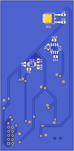
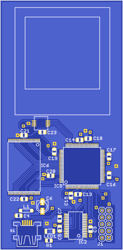
The PCB is double sided and was made using two transparencies aligned carefully on both sides. Unfortunately during aligning some of the ink on the transparencies scratched off which caused some damaged copper areas on the etched PCBs. Luckily nothing serious.
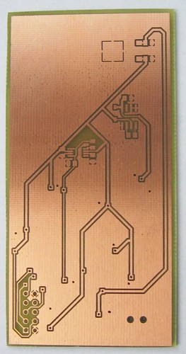
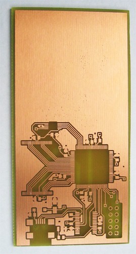
Finally all the components were soldered on both sides:
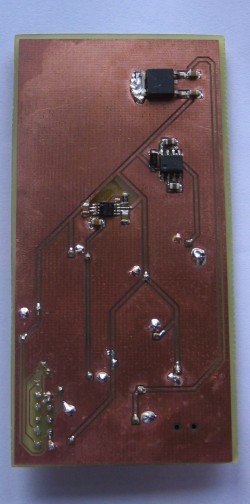
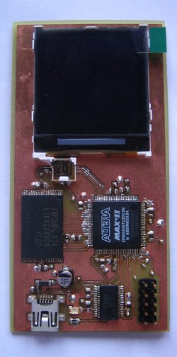
Testing
First tests used the serial interface and some simple logic in the CPLD so that the LCD could be controlled directly from the PC. This way still images could be displayed on the LCD (which has internal RAM).
After that I started working on the memory chip. It took some time before I got the addressing right. The memory uses pages of 2112 bytes, 2048 bytes of data and 64 bytes for error correction, but the pages are addressed by multiples of 4096 to keep the row and column bits separated in the memory addresses. Finally I was able to write the memory from the PC and also read it back, although the lack of flow control caused problems when reading out. However, writing the memory was no problem (since the CPLD is fast enough) and that was the most important.
The MAX II CPLD contains a really small processor (more of a state machine) with 4 instructions. One to send data to the LCD, to set a timer or to wait until the timer expires, and one to jump (branch) to a certain page in memory. Each command or data instruction can carry up to 64 bytes of payload to send to the LCD.
So the flash memory basically contains software for this tiny CPU, a series of commands that send the right data to the LCD and uses the timer instructions to synchronize the framerate.
Here is one of the first working videos:
As you can see it stops at some point, it was not completely stable. The problem was that the ready/~busy output of the flash memory used to indicate when a page has been read into the flash's internal buffer is a asynchronous signal, and I forgot to synchronize this signal in the CPLD. After I fixed this the whole thing worked like a charm.
The MAX II CPLD was filled for 92%, the firmware to upload a video to the flash memory was separate since it did not fit in together with the firmware needed to play the video. Uploading the video was done at a rate of about 200 Kbyte/s, because of the USB1.1 FTDI chip and its maximum bitrate of about 3 MBit/s. So it takes quite some time to put a video in the memory but still acceptable given the hardware.
Finally a longer video, note that the sound was put in later since the device has no means to produce sound (I wish I had included that too :)
